Posts tagged lunch&learn

Autoscaling an Instance Group with Custom Cloud Monitoring Metrics

Overview

Here, we will create a Compute Engine managed instance group that autoscale based on the value of a custom Cloud Monitoring metric.

What you’ll learn

  • Deploy an autoscaling Compute Engine instance group.
  • Create a custom metric used to scale the instance group.
  • Use the Cloud Console to visualize the custom metric and instance group size.

Application Architecture

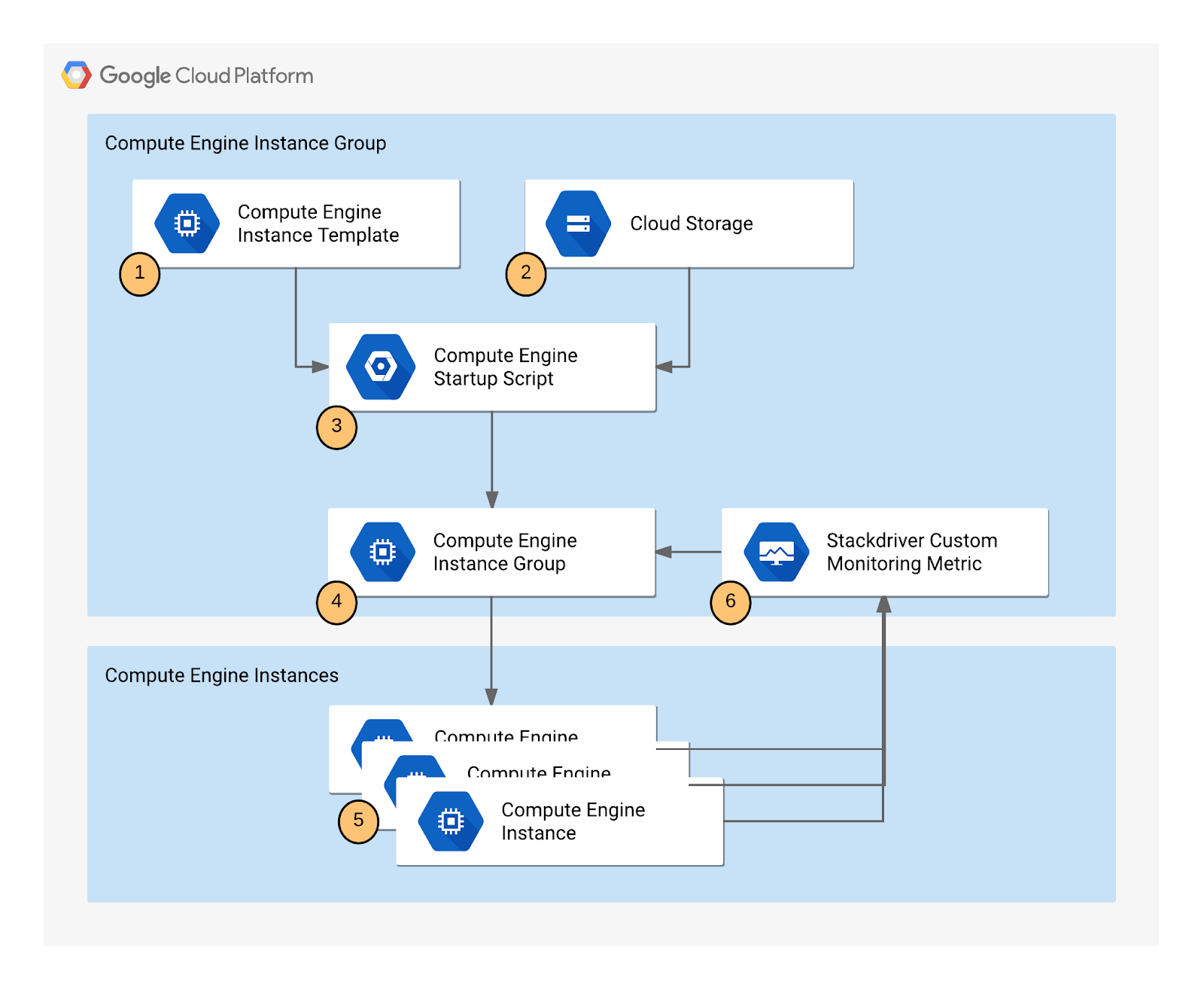
The autoscaling application uses a Node.js script installed on Compute Engine instances. The script reports a numeric value to a Cloud monitoring metric. You do not need to know Node.js or JavaScript for this lab. In response to the value of the metric, the application autoscale the Compute Engine instance group up or down as needed.

The Node.js script is used to seed a custom metric with values that the instance group can respond to. In a production environment, you would base autoscaling on a metric that is relevant to your use case.

The application includes the following components:

  1. Compute Engine instance template – A template used to create each instance in the instance group.
  2. Cloud Storage – A bucket used to host the startup script and other script files.
  3. Compute Engine startup script – A startup script that installs the necessary code components on each instance. The startup script is installed and started automatically when an instance starts. When the startup script runs, it in turn installs and starts code on the instance that writes values to the Cloud monitoring custom metric.
  4. Compute Engine instance group – An instance group that autoscale based on the Cloud monitoring metric values.
  5. Compute Engine instances – A variable number of Compute Engine instances.
  6. Custom Cloud Monitoring metric – A custom monitoring metric used as the input value for Compute Engine instance group autoscaling.
Lab architecture diagram

Task 1. Creating the application

Creating the autoscaling application requires downloading the necessary code components, creating a managed instance group, and configuring autoscaling for the managed instance group.

Uploading the script files to Cloud Storage

During autoscaling, the instance group will need to create new Compute Engine instances. When it does, it creates the instances based on an instance template. Each instance needs a startup script. Therefore, the template needs a way to reference the startup script. Compute Engine supports using Cloud Storage buckets as a source for your startup script. In this section, you will make a copy of the startup script and application files for a sample application used by this lab that pushes a pattern of data into a custom Cloud logging metric that you can then use to configure as the metric that controls the autoscaling behavior for an autoscaling group.

Note: There is a pre-existing instance template and group that has been created automatically by the lab that is already running. Autoscaling requires at least 30 minutes to demonstrate both scale-up and scale-down behavior, and you will examine this group later to see how scaling is controlled by the variations in the custom metric values generated by the custom metric scripts.

Task 2. Create a bucket

  1. In the Cloud Console, scroll down to Cloud Storage from the Navigation menu, then click Create.
  2. Give your bucket a unique name, but don’t use a name you might want to use in another project. For details about how to name a bucket, see the bucket naming guidelines. This bucket will be referenced as YOUR_BUCKET throughout the lab.
  3. Accept the default values then click Create.

Click Confirm for Public access will be prevented pop-up if prompted.

When the bucket is created, the Bucket details page opens.

  1. Next, run the following command in Cloud Shell to copy the startup script files from the lab default Cloud Storage bucket to your Cloud Storage bucket. Remember to replace <YOUR BUCKET> with the name of the bucket you just made:

gsutil cp -r gs://spls/gsp087/* gs://<YOUR BUCKET>

  1. After you upload the scripts, click Refresh on the Bucket details page. Your bucket should list the added files.

Understanding the code components

  • Startup.sh – A shell script that installs the necessary components to each Compute Engine instance as the instance is added to the managed instance group.
  • writeToCustomMetric.js – A Node.js snippet that creates a custom monitoring metric whose value triggers scaling. To emulate real-world metric values, this script varies the value over time. In a production deployment, you replace this script with custom code that reports the monitoring metric that you’re interested in, such as a processing queue value.
  • Config.json – A Node.js config file that specifies the values for the custom monitoring metric and is used in writeToCustomMetric.js.
  • Package.json – A Node.js package file that specifies standard installation and dependencies for writeToCustomMetric.js.
  • writeToCustomMetric.sh – A shell script that continuously runs the writeToCustomMetric.js program on each Compute Engine instance.

Task 3. Creating an instance template

Now create a template for the instances that are created in the instance group that will use autoscaling. As part of the template, you specify the location (in Cloud Storage) of the startup script that should run when the instance starts.

  1. In the Cloud Console, click Navigation menu > Compute Engine > Instance templates.
  2. Click Create Instance Template at the top of the page.
  3. Name the instance template autoscaling-instance01.
  4. Scroll down, click Advanced options.
  5. In the Metadata section of the Management tab, enter these metadata keys and values, clicking the + Add item button to add each one. Remember to substitute your bucket name for the [YOUR_BUCKET_NAME] placeholder:
KeyValue
startup-script-urlgs://[YOUR_BUCKET_NAME]/startup.sh
gcs-bucketgs://[YOUR_BUCKET_NAME]
  1. Click Create.

Task 4. Creating the instance group

  1. In the left pane, click Instance groups.
  2. Click Create instance group at the top of the page.
  3. Name: autoscaling-instance-group-1.
  4. For Instance template, select the instance template you just created.
  5. Set Autoscaling mode to Off: do not autoscale.

You’ll edit the autoscaling setting after the instance group has been created. Leave the other settings at their default values.

  1. Click Create.

Note: You can ignore the Autoscaling is turned off. The number of instances in the group won't change automatically. The autoscaling configuration is preserved. warning next to your instance group.

Task 5. Verifying that the instance group has been created

Wait to see the green check mark next to the new instance group you just created. It might take the startup script several minutes to complete installation and begin reporting values. Click Refresh if it seems to be taking more than a few minutes.

Note: If you see a red icon next to the other instance group that was pre-created by the lab, you can ignore this warning. The instance group reports a warning for up to ten minutes as it is initializing. This is expected behavior.

Task 6. Verifying that the Node.js script is running

The custom metric custom.googleapis.com/appdemo_queue_depth_01 isn’t created until the first instance in the group is created and that instance begins reporting custom metric values.

You can verify that the writeToCustomMetric.js script is running on the first instance in the instance group by checking whether the instance is logging custom metric values.

  1. Still in the Compute Engine Instance groups window, click the name of the autoscaling-instance-group-1 to display the instances that are running in the group.
  2. Scroll down and click the instance name. Because autoscaling has not started additional instances, there is just a single instance running.
  3. In the Details tab, in the Logs section, click Cloud Logging link to view the logs for the VM instance.
  4. Wait a minute or 2 to let some data accumulate. Enable the Show query toggle, you will see resource.type and resource.labels.instance_id in the Query preview box.
 Query preview box
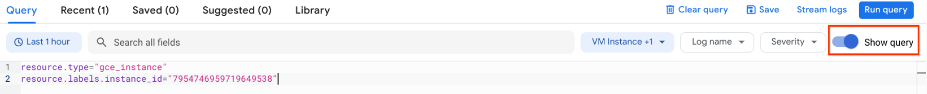
  1. Add “nodeapp” as line 3, so the code looks similar to this:
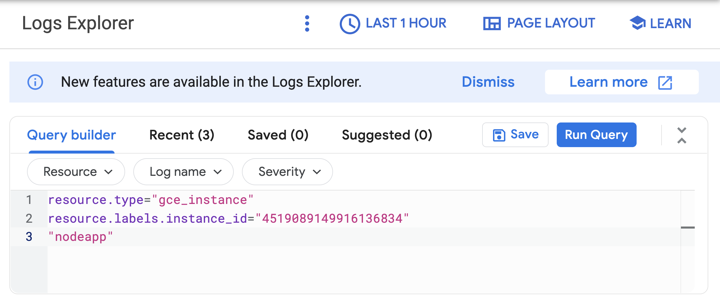
Line 1: resource.type="gce.instance". Line 2: resource.labels.instance_id="4519089149916136834". Line 3: "nodeapp"
  1. Click Run query.

If the Node.js script is being executed on the Compute Engine instance, a request is sent to the API, and log entries that say Finished writing time series data appear in the logs.

Note: If you don’t see this log entry, the Node.js script isn’t reporting the custom metric values. Check that the metadata was entered correctly. If the metadata is incorrect, it might be easiest to restart the lab.

Task 7. Configure autoscaling for the instance group

After you’ve verified that the custom metric is successfully reporting data from the first instance, the instance group can be configured to autoscale based on the value of the custom metric.

  1. In the Cloud Console, go to Compute Engine > Instance groups.
  2. Click the autoscaling-instance-group-1 group.
  3. Under Autoscaling click Configure.
  4. Set Autoscaling mode to On: add and remove instances to the group.
  5. Set Minimum number of instances1 and Maximum number of instances3
  6. Under Autoscaling signals click ADD SIGNAL to edit metric. Set the following fields, leave all others at the default value.
  • Signal typeCloud Monitoring metric new. Click Configure.
  • Under Resource and metric click SELECT A METRIC and navigate to VM Instance > Custom metrics > Custom/appdemo_queue_depth_01.
  • Click Apply.
  • Utilization target150When custom monitoring metric values are higher or lower than the Target value, the autoscaler scales the managed instance group, increasing or decreasing the number of instances. The target value can be any double value, but for this lab, the value 150 was chosen because it matches the values being reported by the custom monitoring metric.
  • Utilization target typeGauge. Click Select.The Gauge setting specifies that the autoscaler should compute the average value of the data collected over the last few minutes and compare it to the target value. (By contrast, setting Target mode to DELTA_PER_MINUTE or DELTA_PER_SECOND autoscales based on the observed rate of change rather than an average value.)
  1. Click Save.

Task 8. Watching the instance group perform autoscaling

The Node.js script varies the custom metric values it reports from each instance over time. As the value of the metric goes up, the instance group scales up by adding Compute Engine instances. If the value goes down, the instance group detects this and scales down by removing instances. As noted earlier, the script emulates a real-world metric whose value might similarly fluctuate up and down.

Next, you will see how the instance group is scaling in response to the metric by clicking the Monitoring tab to view the Autoscaled size graph.

  1. In the left pane, click Instance groups.
  2. Click the builtin-igm instance group in the list.
  3. Click the Monitoring tab.
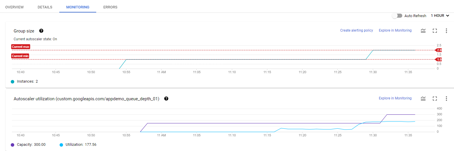
  4. Enable Auto Refresh.

Since this group had a head start, you can see the autoscaling details about the instance group in the autoscaling graph. The autoscaler will take about five minutes to correctly recognize the custom metric and it can take up to ten minutes for the script to generate sufficient data to trigger the autoscaling behavior.

Monitoring tabbed page displaying two monitoring graphs

Hover your mouse over the graphs to see more details.

You can switch back to the instance group that you created to see how it’s doing (there may not be enough time left in the lab to see any autoscaling on your instance group).

For the remainder of the time in your lab, you can watch the autoscaling graph move up and down as instances are added and removed.

Task 9. Autoscaling example

Read this autoscaling example to see how the capacity and number of autoscaled instances can work in a larger environment.

The number of instances depicted in the top graph changes as a result of the varying aggregate levels of the custom metric property values reported in the lower graph. There is a slight delay of up to five minutes after each instance starts up before that instance begins to report its custom metric values. While your autoscaling starts up, read through this graph to understand what will be happening:

Members tabbed page displaying a graph with several data points

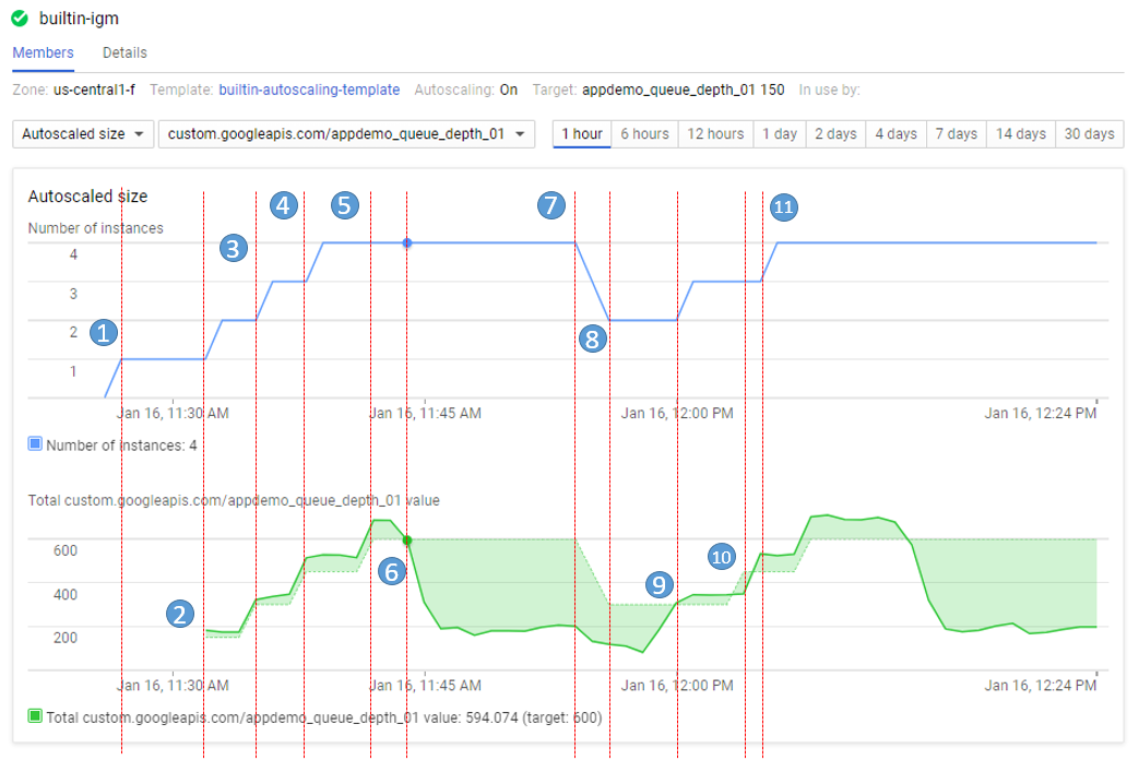
The script starts by generating high values for approximately 15 minutes in order to trigger scale-up behavior.

  • 11:27 Autoscaling Group starts with a single instance. The aggregate custom metric target is 150.
  • 11:31 Initial metric data acquired. As the metric is greater than the target of 150 the autoscaling group starts a second instance.
  • 11:33 Custom metric data from the second instance starts to be acquired. The aggregate target is now 300. As the metric value is above 300 the autoscaling group starts the third instance.
  • 11:37 Custom metric data from the third instance starts to be acquired. The aggregate target is now 450. As the cumulative metric value is above 450 the autoscaling group starts the fourth instance.
  • 11:42 Custom metric data from the fourth instance starts to be acquired. The aggregate target is now 600. The cumulative metric value is now above the new target level of 600 but since the autoscaling group size limit has been reached no additional scale-up actions occur.
  • 11:44 The application script has moved into a low metric 15-minute period. Even though the cumulative metric value is below the target of 600 scale-down must wait for a ten-minute built-in scale-down delay to pass before making any changes.
  • 11:54 Custom metric data has now been below the aggregate target level of 600 for a four-node cluster for over 10 minutes. Scale-down now removes two instances in quick succession.
  • 11:56 Custom metric data from the removed nodes is eliminated from the autoscaling calculation and the aggregate target is reduced to 300.
  • 12:00 The application script has moved back into a high metric 15-minute period. The cumulative custom metric value has risen above the aggregate target level of 300 again so the autoscaling group starts a third instance.
  • 12:03 Custom metric data from the new instance have been acquired but the cumulative values reported remain below the target of 450 so autoscaling makes no changes.
  • 12:04 Cumulative custom metric values rise above the target of 450 so autoscaling starts the fourth instance.

Congratulations!

You have successfully created a managed instance group that autoscale based on the value of a custom metric.

Using Terraform Dynamic Blocks and Built-in Functions to Deploy to AWS

Introduction

Terraform offers a strong set of features to help optimize your Terraform code. Two really useful features are dynamic blocks, which allow you to generate static repeated blocks within resources in Terraform; and built-in functions, which help you manipulate variables and data to suit your needs and help make your Terraform deployments better automated and more fault resilient.

Solution

  1. Check Terraform Status using the version command:terraform version Since the Terraform version is returned, you have validated that the Terraform binary is installed and functioning properly.

Clone Terraform Code and Switch to Proper Directory

  1. The Terraform code required for this lab is below. Copy the same to your working directory.

Examine the Code in the Files

  1. View the contents of the main.tf file using the less command:less main.tf The main.tf file spins up AWS networking components such as a virtual private cloud (VPC), security group, internet gateway, route tables, and an EC2 instance bootstrapped with an Apache webserver which is publicly accessible.
  2. Closely examine the code and note the following:
    • We have selected AWS as our provider and our resources will be deployed in the us-east-1 region.
    • We are using the ssm_parameter public endpoint resource to get the AMI ID of the Amazon Linux 2 image that will spin up the EC2 webserver.
    • We are using the vpc module (provided by the Terraform Public Registry) to create our network components like subnets, internet gateway, and route tables.
    • For the security_group resource, we are using a dynamic block on the ingress attribute to dynamically generate as many ingress blocks as we need. The dynamic block includes the var.rules complex variable configured in the variables.tf file.
    • We are also using a couple of built-in functions and some logical expressions in the code to get it to work the way we want, including the join function for the name attribute in the security group resource, and the fileexists and file functions for the user_data parameter in the EC2 instance resource.
  3. Enter q to exit the less program.
  4. View the contents of the variables.tf file:less variables.tf The variables.tf file contains the complex variable type which we will be iterating over with the dynamic block in the main.tf file.
  5. Enter q to exit the less program.
  6. View the contents of the script.sh file using the cat command:cat script.sh The script.sh file is passed into the EC2 instance using its user_data attribute and the fileexists and file functions (as you saw in the main.tf file), which then installs the Apache webserver and starts up the service.
  7. View the contents of the outputs.tf file:cat outputs.tf The outputs.tf file returns the values we have requested upon deployment of our Terraform code.
    • The Web-Server-URL output is the publicly accessible URL for our webserver. Notice here that we are using the join function for the value parameter to generate the URL for the webserver.
    • The Time-Date output is the timestamp when we executed our Terraform code.

Review and Deploy the Terraform Code

  1. As a best practice, format the code in preparation for deployment:terraform fmt
  2. Validate the code to look for any errors in syntax, parameters, or attributes within Terraform resources that may prevent it from deploying correctly:terraform validate You should receive a notification that the configuration is valid.
  3. Review the actions that will be performed when you deploy the Terraform code:terraform plan Note the Change to Outputs, where you can see the Time-Date and Web-Server-URL outputs that were configured in the outputs.tf file earlier.

Test Out the Deployment and Clean Up

  1. Once the code has executed successfully, view the outputs at the end of the completion message:
    • The Time-Date output displays the timestamp when the code was executed.
    • The Web-Server-URL output displays the web address for the Apache webserver we created during deployment.
    Note: You could also use the terraform output command at any time in the CLI to view these outputs on demand.
  2. Verify that the resources were created correctly in the AWS Management Console:
    • Navigate to the AWS Management Console in your browser.
    • Type VPC in the search bar and select VPC from the contextual menu.
    • On the Resources by Region page, click VPCs.
    • Verify that the my-vpc resource appears in the list.
    • Type EC2 in the search bar and select EC2 from the contextual menu.
    • On the Resources page, click Instances (running).
    • Verify that the instance, which has no name, appears in the list (and is likely still initializing).
    • In the menu on the left, click Security Groups.
    • Verify that the Terraform-Dynamic-SG security group appears in the list.
    • Select the security group to see further details.
    • Click on the Inbound rules tab, and note that three separate rules were created from the single dynamic block used on the ingress parameter in the code.
  3. In the CLI, copy the URL displayed as the Web-Server_URL output value.
  4. In a new browser window or tab, paste the URL and press Enter.
  5. Verify that the Apache Test Page loads, validating that the code executed correctly and the logic within the AWS instance in Terraform worked correctly, as it was able to locate the script.sh file in the folder and bootstrap the EC2 instance accordingly.
  6. In the CLI, tear down the infrastructure you just created before moving on:terraform destroy --auto-approve

Scalability

The term “scalability” is often used as a catch-all phrase to suggest that something is poorly designed or flawed. It’s commonly used in arguments as a way to end discussions, indicating that a system’s architecture is limiting its potential for growth. However, when used positively, scalability refers to a desired property, such as a platform’s need for good scalability.

In essence, scalability means that when resources are added to a system, performance increases proportionally. This can involve serving more units of work or handling larger units of work, such as when datasets grow. In distributed systems, adding resources can also be done to improve service reliability, such as introducing redundancy to prevent failures. A scalable always-on service can add redundancy without sacrificing performance.

Achieving scalability is not easy, as it requires systems to be designed with scalability in mind. Systems must be architected to ensure that adding resources results in improved performance or that introducing redundancy does not adversely affect performance. Many algorithms that perform well under low load and small datasets can become prohibitively expensive when dealing with higher request rates or larger datasets.

Additionally, as systems grow through scale-out, they often become more heterogeneous. This means that different nodes in the system will have varying processing speeds and storage capabilities. Algorithms that rely on uniformity may break down or underutilize newer resources.

Despite the challenges, achieving good scalability is possible if systems are architected and engineered with scalability in mind. Architects and engineers must carefully consider how systems will grow, where redundancy is required, and how heterogeneity will be handled. They must also be aware of the tools and potential pitfalls associated with achieving scalability.

Welcome Metricbeat from the beats family

Deploy Metricbeat on all your Linux, Windows, and Mac hosts, connect it to Elasticsearch and voila: you get system-level CPU usage, memory, file system, disk IO, and network IO statistics, as well as top-like statistics for every process running on your systems. Metricbeats is an open-source shipping agent used to collect and ship operating system and service metrics to one or more destinations, including Logstash.

Step 1 – Install Metricbeat

deb (Debian/Ubuntu/Mint)

sudo apt-get install apt-transport-https
wget -qO - https://artifacts.elastic.co/GPG-KEY-elasticsearch | sudo apt-key add -
echo 'deb https://artifacts.elastic.co/packages/oss-6.x/apt stable main' | sudo tee /etc/apt/sources.list.d/beats.list
sudo apt-get update && sudo apt-get install metricbeat

rpm (CentOS/RHEL/Fedora)

sudo rpm --import https://artifacts.elastic.co/GPG-KEY-elasticsearch
echo "[elastic-6.x]
name=Elastic repository for 6.x packages
baseurl=https://artifacts.elastic.co/packages/oss-6.x/yum
gpgcheck=1
gpgkey=https://artifacts.elastic.co/GPG-KEY-elasticsearch
enabled=1
autorefresh=1
type=rpm-md" | sudo tee /etc/yum.repos.d/elastic-beats.repo

sudo yum install metricbeat

macOS

curl -L -O https://artifacts.elastic.co/downloads/beats/metricbeat/metricbeat-oss-6.7.1-darwin-x86_64.tar.gz 
tar xzvf metricbeat-oss-6.7.1-darwin-x86_64.tar.gz

Windows

  • Download the Metricbeat Windows zip file from the official downloads page.
  • Extract the contents of the zip file into C:\Program Files.
  • Rename the metricbeat-<version>-windows directory to Metricbeat.
  • Open a PowerShell prompt as an Administrator (right-click the PowerShell icon and select Run As Administrator). If you are running Windows XP, you may need to download and install PowerShell.
  • Run the following commands to install Metricbeat as a Windows service:PS > cd 'C:\Program Files\Metricbeat' PS C:\Program Files\Metricbeat> .\install-service-metricbeat.ps1`   If script execution is disabled on your system, you need to set the execution policy for the current session to allow the script to run. For example: PowerShell.exe -ExecutionPolicy UnRestricted -File .\install-service-metricbeat.ps1

My OS isn’t here! Don’t see your system? Check out the official downloads page for more options (including 32-bit versions).

Step 2 – Locate the configuration file

deb/rpm : /etc/metricbeat/metricbeat.yml
mac/win :<EXTRACTED_ARCHIVE>/metricbeat.yml

Step 3 – Configure the Modules

Setup the data you wish to send us, by editing the modules. Examples of these settings are found in, in the same folder as the configuration file. The system status module is enabled by default to collect metrics about your servers, such as CPU usage, memory usage, network IO metrics, and process statistics:

metricbeat.modules:
- module: system
  metricsets:
    - cpu
    - filesystem
    - memory
    - network
    - process
  enabled: true
  period: 10s
  processes: ['.*']
  cpu_ticks: false

  There’s also a large range of modules to collect metrics see here.

Step 4 – Configure output

We’ll be shipping to Logstash so that we have the option to run filters before the data is indexed.
Comment out the elasticsearch output block.

## Comment out elasticsearch output
#output.elasticsearch:
#  hosts: ["localhost:9200"]

Uncomment and change the logstash output to match below.

output.logstash:
    hosts: ["your-logstash-host:your-port"]
    loadbalance: true
    ssl.enabled: true
Step 5 – Validate configuration

Let’s check the configuration file is syntactically correct.

deb/rpm

sudo metricbeat -e -c /etc/metricbeat/metricbeat.yml

macOS

cd <EXTRACTED_ARCHIVE>
./metricbeat -e -c metricbeat.yml

Windows

cd <EXTRACTED_ARCHIVE>
metricbeat.exe -e -c metricbeat.yml
Step 6 – Start metricbeat

Ok, time to start ingesting data!

deb/rpm

sudo systemctl enable metricbeat
sudo systemctl start metricbeat

mac

./metricbeat

Windows

Start-Service metricbeat

With this, you have installed & configured MetricBeat for your environment. Stay tuned for others from the Beats family and also the ElasticSearch Stack Installation.

GCP Series-Getting Started with BigQuery

Overview

In this lab, you load a web server log into a BigQuery table. After loading the data, you query it using the BigQuery web user interface and the BigQuery CLI.

BigQuery helps you perform interactive analysis of petabyte-scale databases, and it enables near-real time analysis of massive datasets. It offers a familiar SQL 2011 query language and functions.

Data stored in BigQuery is highly durable. Google stores your data in a replicated manner by default and at no additional charge for replicas. With BigQuery, you pay only for the resources you use. Data storage in BigQuery is inexpensive. Queries incur charges based on the amount of data they process: when you submit a query, you pay for the compute nodes only for the duration of that query. You don’t have to pay to keep a compute cluster up and running.

Using BigQuery involves interacting with a number of Google Cloud Platform resources, including projects (covered elsewhere in this course), datasets, tables, and jobs. This lab introduces you to some of these resources, and this brief introduction summarizes their role in interacting with BigQuery.

Datasets: A dataset is a grouping mechanism that holds zero or more tables. A dataset is the lowest level unit of access control. Datasets are owned by GCP projects. Each dataset can be shared with individual users.

Tables: A table is a row-column structure that contains actual data. Each table has a schema that describes strongly typed columns of values. Each table belongs to a dataset.

Objectives

  • Load data from Cloud Storage into BigQuery.
  • Perform a query on the data in BigQuery.

Task 1: Load data from Cloud Storage into BigQuery

  1. In the Console, on the Navigation menu () click BigQuery then click Done.
  2. Create a new dataset within your project by selecting your project in the Resources section, then clicking on CREATE DATASET on the right.
  3. In the Create Dataset dialog, for Dataset ID, type logdata.
  4. For Data location, select the continent closest to the region. click Create dataset.
  5. Create a new table in the logdata to store the data from the CSV file.
  6. Click on Create Table. On the Create Table page, in the Source section:
  • For Create table from, choose select Google Cloud Storage, and in the field, typegs://cloud-training/gcpfci/access_log.csv.
  • Verify File format is set to CSV.

Note: When you have created a table previously, the Create from Previous Job option allows you to quickly use your settings to create similar tables.

  1. In the Destination section:
  • For Dataset name, leave logdata selected.
  • For Table name, type accesslog.
  • For Table typeNative table should be selected and unchangeable.
  1. Under Schema section, for Auto detect check the Schema and input Parameters.
  2. Accept the remaining default values and click Create Table.BigQuery creates a load job to create the table and upload data into the table (this may take a few seconds).
  3. (Optional) To track job progress, click Job History.
  4. When the load job is complete, click logdata > accesslog.
  5. On the Table Details page, click Details to view the table properties, and then click Preview to view the table data.Each row in this table logs a hit on a web server. The first field, string_field_0, is the IP address of the client. The fourth through ninth fields log the day, month, year, hour, minute, and second at which the hit occurred. In this activity, you will learn about the daily pattern of load on this web server.

Task 2: Perform a query on the data using the BigQuery web UI

In this section of the lab, you use the BigQuery web UI to query the accesslog table you created previously.

  1. In the Query editor window, type (or copy-and-paste) the following query:
  2. Because you told BigQuery to automatically discover the schema when you load the data, the hour of the day during which each web hit arrived is in a field called int_field_6.select int64_field_6 as hour, count(*) as hitcount from logdata.accesslog group by hour order by hourNotice that the Query Validator tells you that the query syntax is valid (indicated by the green check mark) and indicates how much data the query will process. The amount of data processed allows you to determine the price of the query using theCloud Platform Pricing Calculator.
  3. Click Run and examine the results. At what time of day is the website busiest? When is it least busy?

Task 3: Perform a query on the data using the bq command

In this section of the lab, you use the bq command in Cloud Shell to query the accesslog table you created previously.

  1. On the Google Cloud Platform menu, click Activate Cloud Shell . If a dialog box appears, click Start Cloud Shell.
  2. At the Cloud Shell prompt, enter this command:bq query "select string_field_10 as request, count(*) as requestcount from logdata.accesslog group by request order by requestcount desc" The first time you use the bq command, it caches your Google Cloud Platform credentials, and then asks you to choose your default project. Choose the project that Qwiklabs assigned you to. Its name will look like qwiklabs-gcp- followed by a hexadecimal number.The bq command then performs the action requested on its command line. What URL offered by this web server was most popular? Which was least popular?

Congratulations!

In this lab, you loaded data stored in Cloud Storage into a table hosted by Google BigQuery. You then queried the data to discover patterns.

GCP Series-Getting Started with App Engine

Overview

In this lab, lets create a simple App Engine application using the Cloud Shell local development environment, and then deploy it to App Engine.

Objectives

In this lab, you learn how to perform the following tasks:

  • Preview an App Engine application using Cloud Shell.
  • Launch an App Engine application.
  • Disable an App Engine application.

Task 1: Preview an App Engine application

  1. On the Google Cloud Platform menu, click Activate Cloud Shell . If a dialog box appears, click Start Cloud Shell.
  2. Clone the source code repository for a sample application called guestbook:git clone https://github.com/GoogleCloudPlatform/appengine-guestbook-python
  3. Navigate to the source directory:cd appengine-guestbook-python
  4. List the contents of the directory:ls -l
  5. View the app.yaml file and note its structure:cat app.yaml YAML is a templating language. YAML files are used for configuration of many Google Cloud Platform services, although the valid objects and specific properties vary with the service. This file is an App Engine YAML file with handlers: and libraries:. A Cloud Deployment Manager YAML file, for example, would have different objects.
  6. Run the application using the built-in App Engine development server.dev_appserver.py ./app.yaml The App Engine development server is now running the guestbook application in the local Cloud Shell. It is using other development tools, including a local simulation of Datastore.
  7. In Cloud Shell, click Web preview  > Preview on port 8080 to preview the application.To access the Web preview icon, you may need to collapse the Navigation menu.Result:
  8. Try the application. Make a few entries in Guestbook, and click Sign Guestbook after each entry.
  9. Using the Google Cloud Platform Console, verify that the app is not deployed. In the GCP Console, on the Navigation menu (), click App Engine > Dashboard. Notice that no resources are deployed. The App Engine development environment is local.
  10. To end the test, return to Cloud Shell and press Ctrl+C to abort the App Engine development server.

Task 2: Deploy the Guestbook application to App Engine

Ensure that you are at the Cloud Shell command prompt.

  1. Deploy the application to App Engine using this command:gcloud app deploy ./index.yaml ./app.yaml If prompted for a region, enter the number corresponding to the region that Qwiklabs or your instructor assigned you to. Type Y to continue.
  2. To view the startup of the application, in the GCP Console, on the Navigation menu (), click App Engine > Dashboard.You may see messages about “Create Application”. Keep refreshing the page periodically until the application is deployed.
  3. View the application on the Internet. The URL for your application is https://PROJECT_ID.appspot.com/ where PROJECT_ID represents your Google Cloud Platform project name. This URL is listed in two places:
    • The output of the deploy command: Deployed service [default] to [https://PROJECT_ID.appspot.com]
    • The upper-right pane of the App Engine Dashboard
    Copy and paste the URL into a new browser window.

You may see an INTERNAL SERVER ERROR. If you read to the bottom of the page, you will see that the error is caused because the Datastore Index is not yet ready. This is a transient error. It takes some time for Datastore to prepare and begin serving the Index for guestbook. After a few minutes, you will be able to refresh the page and see the guestbook application interface.

ab92062fcdbf46b7.png

Result: 

Congratulations! You created your first application using App Engine, including exercising the local development environment and deploying it. It is now available on the internet for all users.

Task 3: Disable the application

App Engine offers no option to undeploy an application. After an application is deployed, it remains deployed, although you could instead replace the application with a simple page that says something like “not in service.”

However, you can disable the application, which causes it to no longer be accessible to users.

  1. In the GCP Console, on the Navigation menu (), click App Engine > Settings.
  2. Click Disable application.
  3. Read the dialog message. Enter the App ID and click DISABLE.If you refresh the browser window you used to view to the application site, you’ll get a 404 error.

Congratulations!

In this lab, you deployed an application on App Engine.

GCP Series-Infrastructure Preview

Overview

In this lab, you build a sophisticated deployment in minutes using Marketplace. This lab shows several of the GCP infrastructure services in action and illustrates the power of the platform.

Objectives

  • Use Marketplace to build a Jenkins Continuous Integration environment.
  • Verify that you can manage the service from the Jenkins UI.
  • Administer the service from the Virtual Machine host through SSH.

Task 1: Use Marketplace to build a deployment

Navigate to Marketplace

  1. In the GCP Console, on the Navigation menu ( ), click Marketplace.
  2. Locate the Jenkins deployment by searching for Jenkins Certified by Bitnami.
  3. Click on the deployment and read about the service provided by the software.

Jenkins is an open-source continuous integration environment. You can define jobs in Jenkins that can perform tasks such as running a scheduled build of software and backing up data. Notice the software that is installed as part of Jenkins shown in the left side of the description.

The service you are using, Marketplace, is part of Google Cloud Platform. The Jenkins template is developed and maintained by an ecosystem partner named Bitnami. Notice on the left side a field that says “Last updated.” How recently was this template updated?

The template system is part of another GCP service called Deployment Manager. Later in this class you learn how templates such as this one can be built. That service is available to you. You can create templates like the one you are about to use.

In a class that was previously offered, students would set up a Jenkins environment similar to the one you are about to launch. It took about two days of labs to build the infrastructure that you will achieve in the next few minutes.

Launch Jenkins

  1. Click Launch on Compute Engine.
  2. Verify the deployment, accept the terms and services and click Deploy.
  3. Click Close on the Welcome to Deployment Manager window.

It will take a minute or two for Deployment Manager to set up the deployment. You can watch the status as tasks are being performed. Deployment Manager is acquiring a virtual machine instance and installing and configuring software for you. You will see jenkins-1 has been deployed when the process is complete.

Deployment Manager is a GCP service that uses templates written in a combination of YAML, python, and Jinja2 to automate the allocation of GCP resources and perform setup tasks. Behind the scenes a virtual machine has been created. A startup script was used to install and configure software, and network Firewall Rules were created to allow traffic to the service.

Task 2: Examine the deployment

In this section, you examine what was built in GCP.

View installed software and login to Jenkins

  1. In the right pane, click More about the software to view additional software details. Look at all the software that was installed.
  2. Copy the Admin user and Admin password values to a text editor.
  3. Click Visit the site to view the site in another browser tab. If you get an error, you might have to reload the page a couple of times.
  4. Log in with the Admin user and Admin password values.
  5. After logging in, you will be asked to Customize Jenkins. Click Install suggested plugins, and then click Restart after the installation is complete. The restart will take a couple of minutes.

Note: If you are getting an installation error, retry the installation and if it fails again, continue past the error and save and finish before restarting. The code of this solution is managed and supported by Bitnami.

Explore Jenkins

  1. In the Jenkins interface, in the left pane, click Manage Jenkins. Look at all of the actions available. You are now prepared to manage Jenkins. The focus of this lab is GCP infrastructure, not Jenkins management, so seeing that this menu is available is the purpose of this step.
  2. Leave the browser window open to the Jenkins service. You will use it in the next task.

Now you have seen that the software is installed and working properly. In the next task you will open an SSH terminal session to the VM where the service is hosted, and verify that you have administrative control over the service.

Task 3: Administer the service

View the deployment and SSH to the VM

  1. In the GCP Console, on the Navigation menu( ), click Deployment Manager.
  2. Click jenkins-1.
  3. Click SSH to connect to the Jenkins server.

The Console interface is performing several tasks for you transparently. For example, it has transferred keys to the virtual machine that is hosting the Jenkins software so that you can connect securely to the machine using SSH.

Shut down and restart the services

  1. In the SSH window, enter the following command to shut down all the running services:
sudo /opt/bitnami/ctlscript.sh stop
  1. Refresh the browser window for the Jenkins UI. You will no longer see the Jenkins interface because the service was shut down.
  2. In the SSH window, enter the following command to restart the services:
sudo /opt/bitnami/ctlscript.sh restart
  1. Return to the browser window for the Jenkins UI and refresh it. You may have to do it a couple of times before the service is reachable.
  2. In the SSH window, type exit to close the SSH terminal session.

Congratulations!

In a few minutes you were able to launch a complete Continuous Integration solution. You demonstrated that you had user access through the Jenkins UI, and you demonstrated that you had administrative control over Jenkins by using SSH to connect to the VM where the service is hosted and by stopping and then restarting the services.

15 Infrastructure as Code tools you can use to automate your deployments

There are MANY tools that can help you automate your infrastructure. This post highlights a few of the more popular tools out there and some of their differentiating features.

Configuration Orchestration vs. Configuration Management

The first thing that should be clarified is the difference between “configuration orchestration” and “configuration management” tools, both of which are considered IaC tools and are included on this list.

Configuration orchestration tools, which include Terraform and AWS CloudFormation, are designed to automate the deployment of servers and other infrastructure.

Configuration management tools like Chef, Puppet, and the others on this list help configure the software and systems on this infrastructure that has already been provisioned.

Configuration orchestration tools do some level of configuration management, and configuration management tools do some level of orchestration. Companies can and many times use both types of tools together.

All right, on to the tools!

Terraform

Terraform logo

Terraform is an infrastructure provisioning tool created by Hashicorp. It allows you to describe your infrastructure as code, creates “execution plans” that outline exactly what will happen when you run your code, builds a graph of your resources, and automates changes with minimal human interaction.

Terraform uses its own domain-specific language (DSL) called Hashicorp Configuration Language (HCL). HCL is JSON-compatible and is used to create these configuration files that describe the infrastructure resources to be deployed.

Terraform is cloud-agnostic and allows you to automate infrastructure stacks from multiple cloud service providers simultaneously and integrate other third-party services.

You even can write Terraform plugins to add new advanced functionality to the platform.

AWS CloudFormation

Similar to Terraform, AWS CloudFormation is a configuration orchestration tool that allows you to code your infrastructure to automate your deployments.

Primary differences lie in that CloudFormation is deeply integrated into and can only be used with AWS, and CloudFormation templates can be created with YAML in addition to JSON.

CloudFormation allows you to preview proposed changes to your AWS infrastructure stack and see how they might impact your resources, and manages dependencies between these resources.

To ensure that deployment and updating of infrastructure is done in a controlled manner, CloudFormation uses Rollback Triggers to revert infrastructure stacks to a previous deployed state if errors are detected.

You can even deploy infrastructure stacks across multiple AWS accounts and regions with a single CloudFormation template. And much more.

We’ve written a ton of CloudFormation templates, so we’ll dig much deeper into this in future posts.

Azure Resource Manager and Google Cloud Deployment Manager

azure resource manager

If you’re using Microsoft Azure or Google Cloud Platform, these cloud service providers offer their own IaC tools similar to AWS CloudFormation.

Azure Resource Manager allows you to define the infrastructure and dependencies for your app in templates, organize dependent resources into groups that can be deployed or deleted in a single action, control access to resources through user permissions, and more.

GCP Deployment Manager

Google Cloud Deployment Manager offers many similar features to automate your GCP infrastructure stack. You can create templates using YAML or Python, preview what changes will be made before deploying, view your deployments in a console user interface, and much more.

Chef

chef logo

Chef is one of the most popular configuration management tools that organizations use in their continuous integration and delivery processes.

Chef allows you to create “recipes” and “cookbooks” using its Ruby-based DSL. These recipes and cookbooks specify the exact steps needed to achieve the desired configuration of your applications and utilities on existing servers. This is called a “procedural” approach to configuration management, as you describe the procedure necessary to get your desired state.

Chef is cloud-agnostic and works with many cloud service providers such as AWS, Microsoft Azure, Google Cloud Platform, OpenStack, and more.

Puppet

puppetlogo

Similar to Chef, Puppet is another popular configuration management tool that helps engineers continuously deliver software.

Using Puppet’s Ruby-based DSL, you can define the desired end state of your infrastructure and exactly what you want it to do. Then Puppet automatically enforces the desired state and fixes any incorrect changes.

This “declarative” approach – where you declare what you want your configuration to look like, and then Puppet figures out how to get there – is the primary difference between Puppet and Chef. Also, Puppet is mainly directed toward system administrators, while Chef primarily targets developers.

Puppet integrates with the leading cloud providers like AWS, Azure, Google Cloud, and VMware, allowing you to automate across multiple clouds.

Saltstack

Saltstack_logo

Saltstack differentiates itself from tools like Chef and Puppet by taking an “infrastructure as data” approach, instead of “infrastructure as code.”

What this means is that Saltstack’s declarative configuration patterns, while written in Python, are language-agnostic (i.e. you don’t need to learn a specific DSL to create them) and thus are more easily read and understood.

Another differentiator is that Saltstack supports remote execution of commands, whereas Chef and Puppet’s configuration code needs to be pulled from their servers.

Ansible

Ansible logo

Ansible is an infrastructure automation tool created by Red Hat, the huge enterprise open source technology provider.

Ansible models your infrastructure by describing how your components and system relate to one another, as opposed to managing systems independently.

Ansible doesn’t use agents, and its code is written in YAML in the form of Ansible Playbooks, so configurations are very easy to understand and deploy.

You can also extend Ansible’s functionality by writing your own Ansible modules and plugins.

Juju

Juju is an IaC tool brought to you by Canonical, the company behind Ubuntu.

You can create Juju charms, which are sets of scripts that deploy and operate software, and bundles, which are collections of charms linked together to deploy entire app infrastructures all at once.

You can then use Juju to manage and apply changes to your infrastructure with simple commands.

Juju works with bare metal, private clouds, multiple public cloud providers, as well as other orchestration tools like Puppet and Chef.

Docker

docker logo

Docker helps you easily create containers that package your code and dependencies together so your applications can run in any environment, from your local workstation to any cloud service provider’s servers.

YAML is used to create configuration files called Dockerfiles. These Dockerfiles are the blueprints to build the container images that include everything – code, runtime, system tools and libraries, and settings – needed to run a piece of software.

Because it increases the portability of applications, Docker has been especially valuable in organizations who use hybrid or multi-cloud environments.

The use of Docker containers has grown exponentially over the past few years and many consider it to be the future of virtualization.

Vagrant

Vagrant is another IaC tool built by HashiCorp, the makers of Terraform.

The difference is that Vagrant focuses on quickly and easily creating development environments that use a small amount of virtual machines, instead of large cloud infrastructure environments that can span hundreds or thousands of servers across multiple cloud providers.

Vagrant runs on top of virtual machine solutions from VirtualBox, VMware, AWS, and any other cloud provider, and also works well with tools like Chef and Puppet.

Pallet

Pallet logo

Pallet is an IaC tool used to automate infrastructure in the cloud, on server racks, or virtual machines, and provides a high level of environment customization.

You can run Pallet from anywhere, and you don’t have to set up and maintain a central server.

Pallet is written in Clojure, runs in a Java Virtual Machine, and works with AWS, OpenStack, VirtualBox, and others, but not Azure nor GCP.

You can use Pallet to start, stop, and configure nodes, deploy projects, and even run administrative tasks.

(R)?ex

(R)?ex is an open-source, weirdly-spelled infrastructure automation tool. “(R)?ex” is too hard to type over and over again, so I’m going to spell it “Rex” from now on.

Rex has its own DSL for you to describe your infrastructure configuration in what are called Rexfiles, but you can use Perl to harness Rex’s full power.

Like Ansible, Rex is agent-less and uses SSH to execute commands and manage remote hosts. This makes Rex easy to use right away.

CFEngine

CFEngine is one of the oldest IaC tools out there, with its initial release in 1993.

CFEngine allows you to define the desired states of your infrastructure using its DSL. Then its agents monitor your environments to ensure that their states are converging toward the desired states, and reports the outcomes.

It’s written in C and claims to be the fastest infrastructure automation tool, with execution times under 1 second.

NixOS

NixOS is a configuration management tool that aims to make upgrading infrastructure systems as easy, reliable, and safe as possible.

The platform does this by making configuration management “transactional” and “atomic.” What this means is that if an upgrade to a new configuration is interrupted for some reason, the system will either boot up in the new or old configuration, thus staying stable and consistent.

nix logo

NixOS also makes it very easy to rollback to a prior configuration, since new configuration files don’t overwrite old ones.

These configuration files are written in Nix expression language, its own unique functional language.

Conclusion

So there you have it. Check out these configuration orchestration and management tools that you can use to implement Infrastructure as Code and help you automate your infrastructure.

This list is by no means exhaustive but it should give you a starting point for tools that you can use during your IaC journey.

Containers or serverless? Consider this..

Every day in our technology world, we see a never-ending battle for the technology platform of choice. One among them is serverless vs. container that looks to be gaining steam. Both of them have their advantages, disadvantages, and proponents. Google, Cisco, and IBM are pushing the container approach, whereas Serverless is being pushed heavily by major public cloud providers like AWS, Azure & GCP (all these cloud operators also offer services for both native containers and Kubernetes).

As we saw in the growth of cloud, and now containers, this migration isn’t always seamless. In fact, we’ve seen both Microsoft (Azure Stack) and Amazon (Outposts) introduce products to work within our existing data center. Migrations haven’t returned the value that was promised because cost, security, regulatory needs, and complexity haven’t been as seamless as we all once imagined. The move to containers and serverless architectures will face some of the same dilemmas as cloud, but this is setting itself up to be 2019’s enterprise.

Unlike before, today’s industries wish to move to the latest and greatest technology quickly, usually because of significant advantages in price, time and simplicity once deployed. And, it’s simply more fun as an engineer to play and learn as the tech grows itself.

Now let’s examine some of the differences between the two latest and greatest:

New Apps:

Containers are useful when the application require multiple instances running parallelly. The hard parameters on the execution time also limit long-running and complicated processes from finishing, making large data crunching particularly challenging, whereas with a container the spawning of new containers to split workload is simpler and handled automatically.

Serverless, on the other hand lends itself to exciting possibilities for new applications, especially in the IoT, physical security and world of chatbots. The ability to use triggers to kick off various actions (without having any underlying infrastructure) and grow at scale allows for both a cost-effective and simplified management. Applications that are listening for triggers can execute code in an IoT environment as it changes, reducing the costs, and simplifying the software management for a company that may not have a giant DevOps staff.

Native Cloud Apps:

Migrating existing native cloud applications is basically a question about the nature of the application itself.  If you’ve purpose-built your applications with a singular public cloud vendor, then integrating and even migrating applications to serverless becomes very easy. All the major serverless platforms have built-in hooks to other native cloud services and allow for quick and seamless architecture changes. Specifically, applications that relied upon orchestration tools for quick scale up and down may find the simplicity that serverless provides to be very advantageous.

The argument for containers is like that of serverless: gain functionality from existing cloud services and improve orchestrated scaling. But the difference is in the maturity of containers versus serverless.  Container testing is much more advanced, and the number of people with the required skill set to efficiently architect the solution is far greater than with serverless. But most applications today are hybrid or multi-cloud/multi-architecture, and the differences here vary even greater.

Legacy Hybrid/On-Prem Apps:

The last ten years have shown the world the complexity with lift and shift, and the high costs associated with such a cloud strategy. Instead, we’ve seen the rise of Hybrid applications that run on multiple different clouds and may work with the existing on-premise solution providing some functionality.  Serverless can provide a faster path to the cloud; however, only if the time to architect the solution correctly has been applied. Legacy applications that perform on-demand quick checks and tasks can easily be ported towards a serverless solution, thus reducing the complexity of managing a larger, more complicated code base and physical footprint – and several these legacy mainframe tasks have already been ported successfully into serverless apps.

Containers offer a more straightforward fashion to migrating your legacy technologies, with far less architectural or vendor dependence.  The single biggest long-term hurdle for serverless growth is the vendor lock-in to one of the big 3 (Amazon, Microsoft & Google), as the technologies are not yet truly portable. Contrast that with Kubernetes running on top of various clouds to reduce the need to use a particular cloud vendor and adoption by companies like Cisco and IBM as part of their overall cloud strategy.  By contrast, the serverless approach is largely platform dependent, and thus being pushed heavily by the incumbent IaaS providers to keep you on their platform.

Summary:

In the short- term, it seems that serverless is still in its early stages and best suited to purpose-built applications and in specific domains. But it has fabulous upside and value as an alternative approach to handling large-scale complexity and heavy architecture costs. The recent announcement by Amazon at AWS hints they see a similar set of needs to complement Lambda and other serverless technologies in the future and the keen interest in serverless will only sprout up solutions to these problems over time.